
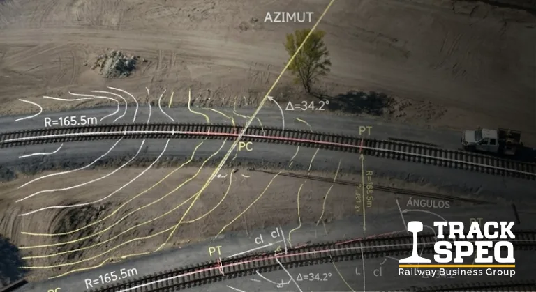
An industrial track can have new rail, ties in good condition and complete fastenings, and still perform poorly. Cars bind on the same curve, the railcar mover slips on the same stretch, side wear concentrates on one rail and low-speed derailments keep happening at the same switch. In most of these cases the root cause lies in railway track geometry: the shape of the track in plan, in profile and in cross-section, and how well that shape holds up with use.
Geometry determines how much a unit can pull, how fast it can travel safely, how long the rail lasts and how much maintenance attention each section requires. It is set in the design, but it is lost in operation: the ballast becomes fouled, drainage fails, fastenings loosen and the track slowly deforms until the defect shows up as a switching problem.
This article is written for the people who work on the track: the yard supervisor, the maintenance manager, the track engineer and the site resident engineer. It covers the parameters that most affect industrial yard operations, what happens when each one goes out of range, and which field signs indicate that it is already happening.
What railway track geometry covers and why it is reviewed as a system
Mexican standard NOM-003-ARTF-2023 defines track geometry as the set of requirements used in the design, construction and maintenance of the track: gauge, alignment, surface (leveling), outer-rail elevation on curves, running surface and speed limits. The standard applies to general railway lines; industrial yards are not legally bound by it, but its definitions and criteria are the most organized technical reference available in Mexico.
Geometric parameters depend on one another. A section with poor leveling transfers more load to one rail than to the other; that rail wears faster, the gauge widens and the alignment begins to lose uniformity. Correcting only the visible symptom—for example, adjusting the gauge without checking leveling or ballast—brings the track back into range for only a short time.
The standard itself sets the work sequence for maintaining the track: before it is aligned, it must be leveled and have the correct gauge. That sequence sums up the logic of the system. Geometry is read as a whole and corrected from the bottom up: subgrade and drainage, ballast, leveling, gauge and alignment.
In plan, the track consists of straight sections or tangents, circular curves and transition curves or spirals, which connect a tangent to a curve by gradually increasing curvature. In profile, it consists of graded sections and vertical curves that join different grades. Each of these elements has its own consequences for operations.
Curve radius: what changes at the wheel, the rail and the switching operation
The sharper the curve, the greater the force with which the wheel flange presses against the outer rail. This has three direct effects: it increases the rolling resistance of the cut of cars, accelerates side wear on the outer rail and the flange, and raises the risk of a wheel climbing the rail when other defects are present.
In industrial yards, the radius is usually constrained by the space available inside the plant. It is common to find sharper curves than on mainline track, because the site leaves no other option. A sharp curve can be operated well, but it requires more frequent maintenance and leaves less margin for error in the other parameters. A slightly wide gauge or a loose fastening that would go unnoticed on tangent track can end in a derailment on a sharp curve.
The radius also determines which cars can enter the plant. Each type of car and coupler has a minimum negotiable radius. If a plant starts receiving longer cars than the original design anticipated, a curve that worked for years can become a risk point without the track having changed at all.
Degree of curvature and radius: two ways of expressing the same curve
NOM-003-ARTF-2023 expresses curvature as degree of curvature: the angle subtended by a 20 m chord. Under that convention, a 1-degree curve has a radius of about 1,146 m, and the radius decreases in inverse proportion to the degree: a 10-degree curve has a radius of around 115 m.
Equipment manuals of U.S. origin use a different convention, based on a 100-foot chord. The numerical value of the degree does not match between the two systems, even though it is written the same way. Before using a manufacturer’s tractive capacity table with curvature data measured in the field, confirm which convention each figure uses. Mixing them produces tractive effort calculations that look correct but are not.
Gauge on curves and side wear
Gauge is the distance between the inner faces of the rails, measured 16 mm (5/8 inch) below the running surface. The standard value is 1,435 mm, and the standard sets minimums and maximums by track class. On curves, side wear on the outer rail progressively widens the gauge: the measurement increases even though the track has not moved, because the rail has lost material on the contact face.
Wide gauge on a curve is one of the defects with the highest ratio between ease of detection and consequence. It is measured with a simple instrument, and when it goes out of range it can allow a wheel to drop between the rails. That is why sharp curves should be measured more often than tangent track in the same yard.
Grade: the parameter that consumes the most pulling capacity
In an industrial yard, grade is the geometric variable with the greatest impact on switching equipment. The effect is very large even at inclines that look flat to the naked eye. The Shuttlewagon operating manual for the SWX series indicates that a 0.5% grade reduces pulling capacity by about half compared with level track, a 1.0% grade by about two-thirds and a 1.5% grade by about three-quarters.
The same manual estimates that each degree of curve is roughly equivalent to one less car of pulling capacity, and warns that when grade and curvature coincide, their effects add up. Rain, frost or rail contamination reduce adhesion even further. A curve on a grade with wet rail is the most demanding scenario in a yard, and it is exactly where slipping and repeated moves tend to concentrate.
The operational consequence is direct: a unit that moves a cut of cars without trouble on the level section may not be able to start it on the graded section. The plant compensates by splitting the cut, making more trips or using more equipment, and each of those solutions lengthens the switching cycle. If the grade was not in the design and appeared through ground settlement or poor leveling, the cost is paid on every shift without anyone identifying it as a track problem.
Grade and car storage
Grade also matters when cars are standing still. A car parked on an incline tends to roll if the handbrakes fail or were not applied correctly. That is why storage and loading areas should be located on level sections whenever the layout allows, and graded sections should be equipped with wheel chocks and track protection devices such as derails. The actual grade of each storage track should be measured and recorded, not assumed.
Alignment and leveling: defects you feel before you see them
Alignment describes how uniform the track’s path is in plan. On tangent track, the track must be straight; on a curve, the curvature must remain constant. The practical way to measure it is with a string line stretched along the rail and measurement of the mid-ordinate, which is the distance between the string and the rail at the midpoint. NOM-003-ARTF-2023 sets maximum mid-ordinate deviations over 10 m and 20 m chords by track class.
Irregular alignment causes the car to advance with lateral movements that load each rail alternately. This accelerates wheel and rail wear, loosens fastenings and displaces ballast. On a curve, an alignment irregularity means that at that point the curve is sharper than it should be, with all the consequences of a small radius concentrated in a few meters.
Leveling describes the vertical position of the rails: the profile along the track and the cross-level between the two rails. The most relevant defects are localized dips, which tend to appear at joints or in poorly drained areas, and twist (warp), which is the variation in cross-level over a short distance. Twist is especially dangerous because it can leave a wheel without enough load on the rail, and an unloaded wheel climbs the rail easily.
These defects are felt before they are measured. The operator feels the unit rocking, the brakeman sees a car swaying more on a certain section, and the track crew finds displaced ballast or ties that move under load. These field observations are useful information and should be recorded by location, because they point to where to measure first.
Superelevation on yard tracks: when it helps and when it gets in the way
Superelevation, also called cant, is the height difference between the outer rail and the inner rail on a curve. Its purpose is to offset the centrifugal force that arises when equipment travels through the curve. NOM-003-ARTF-2023 calculates superelevation from operating speed and degree of curvature, establishes that the outer rail may never sit below the inner rail, and limits maximum outer-rail elevation to 152 mm for any track class, unless specially authorized.
In the standard’s formula, superelevation increases with the square of the speed. This has a practical implication for industrial yards: at low switching speeds, the required superelevation is small. A yard curve with excessive superelevation overloads the inner rail, wears that rail and can make it harder to start a cut of cars that has stopped inside the curve.
The transition also matters. Superelevation must increase gradually at the curve entry and decrease the same way at the exit. An abrupt change in cross-level creates twist, which is precisely one of the defects with the highest derailment risk. When a yard curve is rehabilitated, superelevation and its transition should be reviewed as part of the project rather than left as they were out of habit.
Track centers, clearance and working space
Geometry also includes the relationship between the track and its surroundings. The distance between centerlines of parallel tracks, the clearance envelope (the free space around the car that no structure may encroach upon) and the side walkways for personnel determine whether a move can be performed safely.
In plants that grew in stages, it is common to find added tracks with reduced spacing, platforms or structures too close to the rail and installations that encroach on the clearance envelope. Each of these conditions turns a routine move into a hazardous one for personnel. A brakeman who needs to step off a car or walk alongside the track needs clear space, and that space is defined in the layout, not in the procedure.
Track spacing also limits switch operation and access for maintenance machinery. A track too close to another one makes it impossible to work on one without interrupting its neighbor, which lengthens maintenance windows and forces more downtime than necessary. Spacing and clearance values should be taken from the railroad concessionaire’s specifications when the track connects to the network, and from the plant’s project in all other cases.
Field signs that geometry is already affecting operations
Geometry rarely fails all at once. It degrades progressively, and the yard crew sees the consequences long before anyone measures. The most useful signs are those that repeat at the same location:
- Recurring slipping on the same section: usually indicates a steeper grade than planned, a sharper curve due to irregular alignment, or contaminated rail. If the unit always slips at the same spot, the problem is the track, not the operator.
- Side wear concentrated on one rail: expected on a curve, but if it progresses quickly it points to wide gauge, inadequate superelevation or irregular alignment. Wear widens the gauge and the cycle accelerates.
- Cars that rock or bounce at one point: a typical sign of a dip or twist, often associated with joints or poor drainage. This is the kind of defect that precedes a low-speed derailment.
- Fastenings that always loosen on the same section: indicates lateral track movement, which can come from irregular alignment or insufficient shoulder ballast.
- Repeated derailments at a switch: usually combine wear of turnout components with leveling or gauge defects in the switch area.
- Standing water next to the track after rain: not a geometric defect yet, but it will become one. Poor drainage is the most frequent cause of lost leveling.
This list is a starting point and does not cover every case. What matters is that each observation is recorded with its location, because geometry is corrected section by section, and an organized field record makes it possible to prioritize work where it most affects operations.
Systematic measurement is the next step. For gauge and cross-level, well-calibrated hand tools are enough, such as the track gauges and levels for field measurement that let you check both parameters on the same walk. For alignment, a string line and mid-ordinate measurement are used. What makes measurement useful is frequency and record-keeping: a single reading shows the current condition, but a series of readings at the same point shows how fast the track is degrading.
When geometry is reviewed together with yard design, the capacity and layout criteria for a switching yard help distinguish which problems can be fixed with maintenance and which require changing the layout. A grade that comes from the terrain or a curve limited by plant space cannot be solved with leveling; it requires an engineering decision.
At Track Speq, we review industrial track geometry as part of maintenance assessments and rehabilitation projects: field measurement, identification of critical sections and an intervention plan prioritized by operational impact. If your yard has a section where problems keep recurring, the most useful first step is to measure it and review the results together. Contact: en.trackspeq.com · ventas@trackspeq.com · +52 81 1600 5603.
